Shougang Hierro Peru Mining Complex
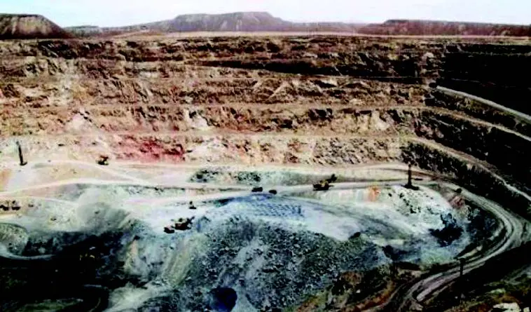
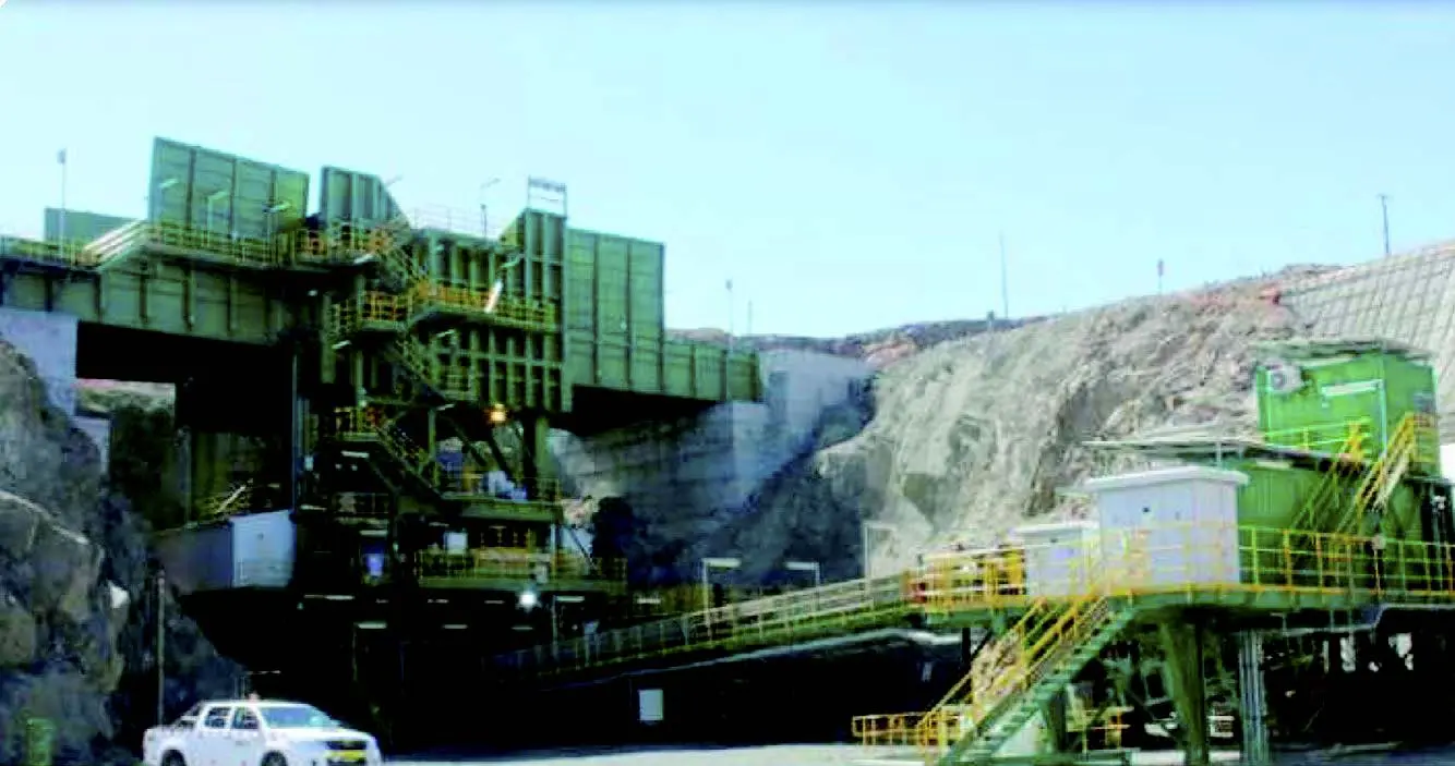
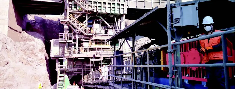
The Shougang Hierro Perú mining complex is in Marcona, and comprises three areas: Mina, San Nicolás and San Juan. In the Mine area, a partial view of which is given below, mineral exploration and exploitation works are carried out under the open pit system.
Semi-mobile Preliminary Crusher
The ore in the new Mina area is taken to the preliminary semi-mobile crushing plant, with a capacity of 2,500 t/h. At the top of the plant is a hopper where dump trucks unload, which drops the ore into the cone crusher.
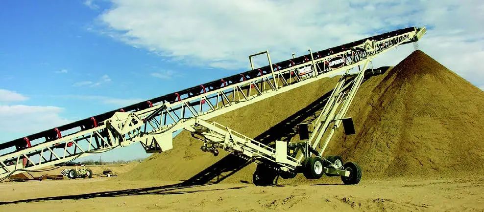
Discharge Belt GSSF 2000×47.7
It is a strip of 2000 mm wide and 47.7 m long. This girdle receives crushed ore vertically and unloads it with horizontal velocity in other longer belts, protecting them, like a sacrificial belt, from intense wear.
This belt can work at a mass flow of up to 3050 t/h but currently operates at 2,800 t/h due to limitations of the following belts. The belt transports high-grade and low-grade ore at the same mass flow, regulating the speed.
The Sacrificial Belt Drive
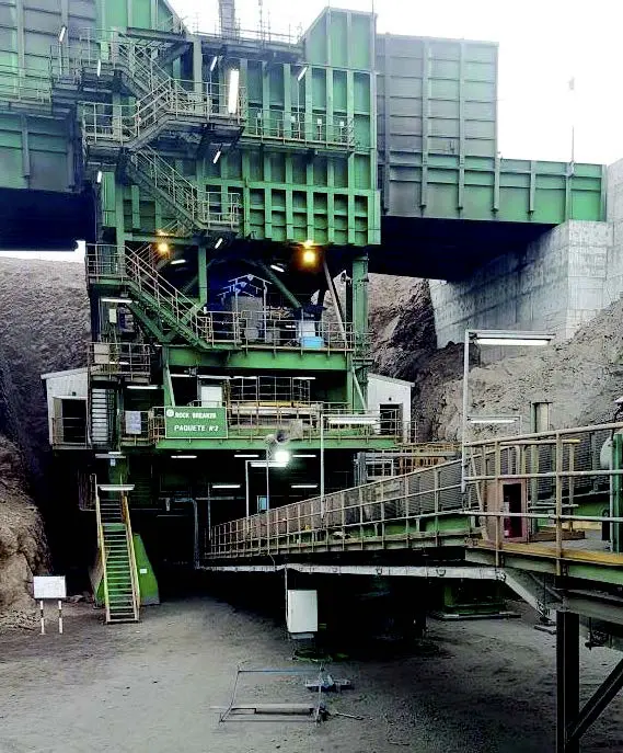
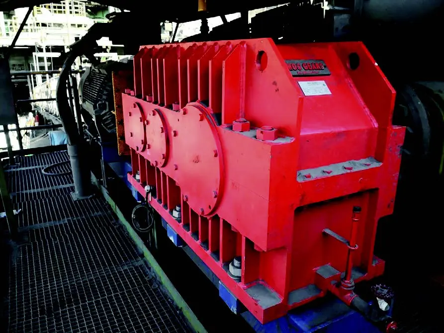
It is a motor system + quick coupling + reducer + slow coupling + base. The slow coupling is rigid and fits into the drive pulley shaft of the belt, and the base is linked to the frame of the belt by a cylindrical joint, thus forming an isostatic assembly, shown here in elevation.
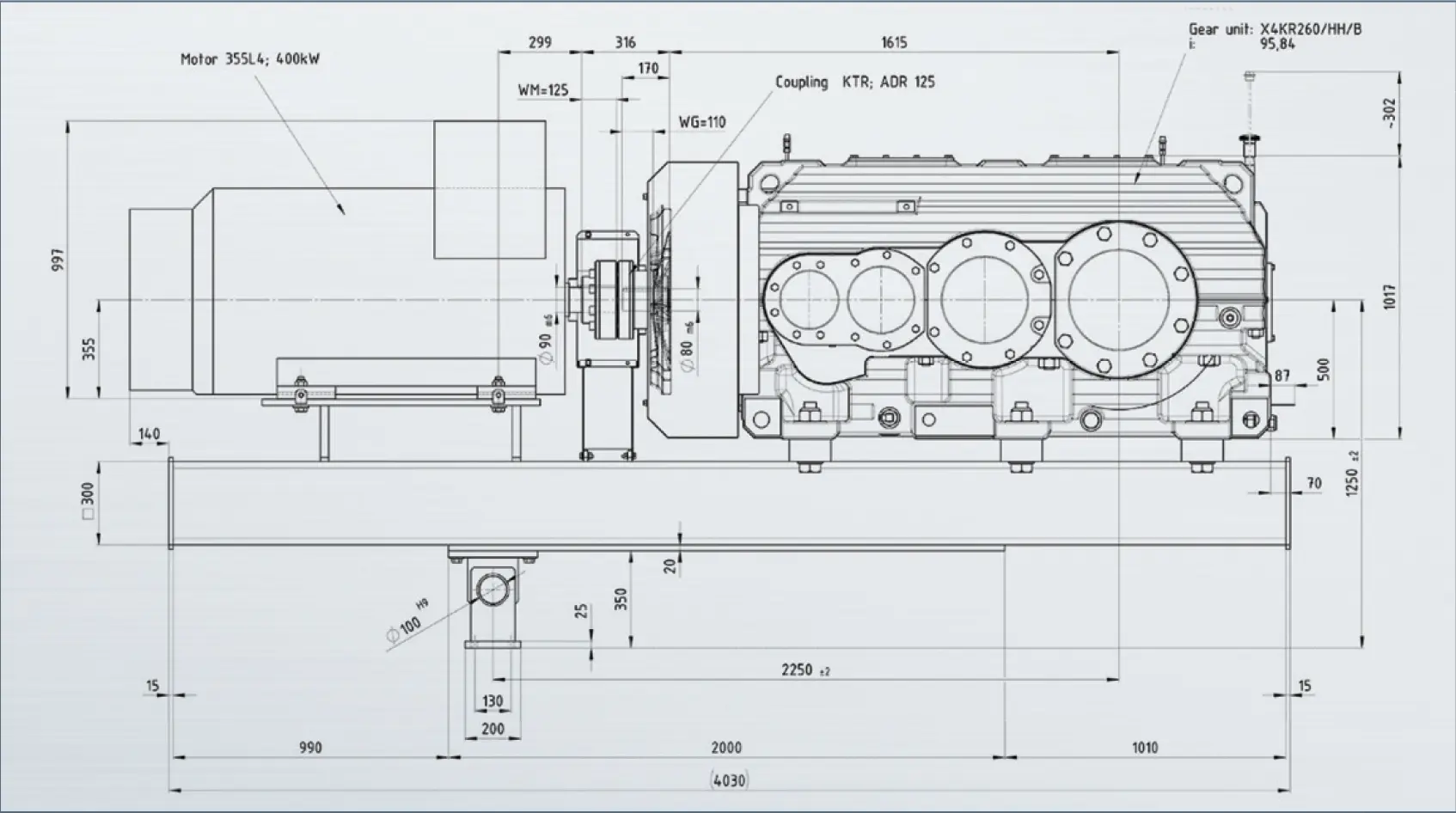
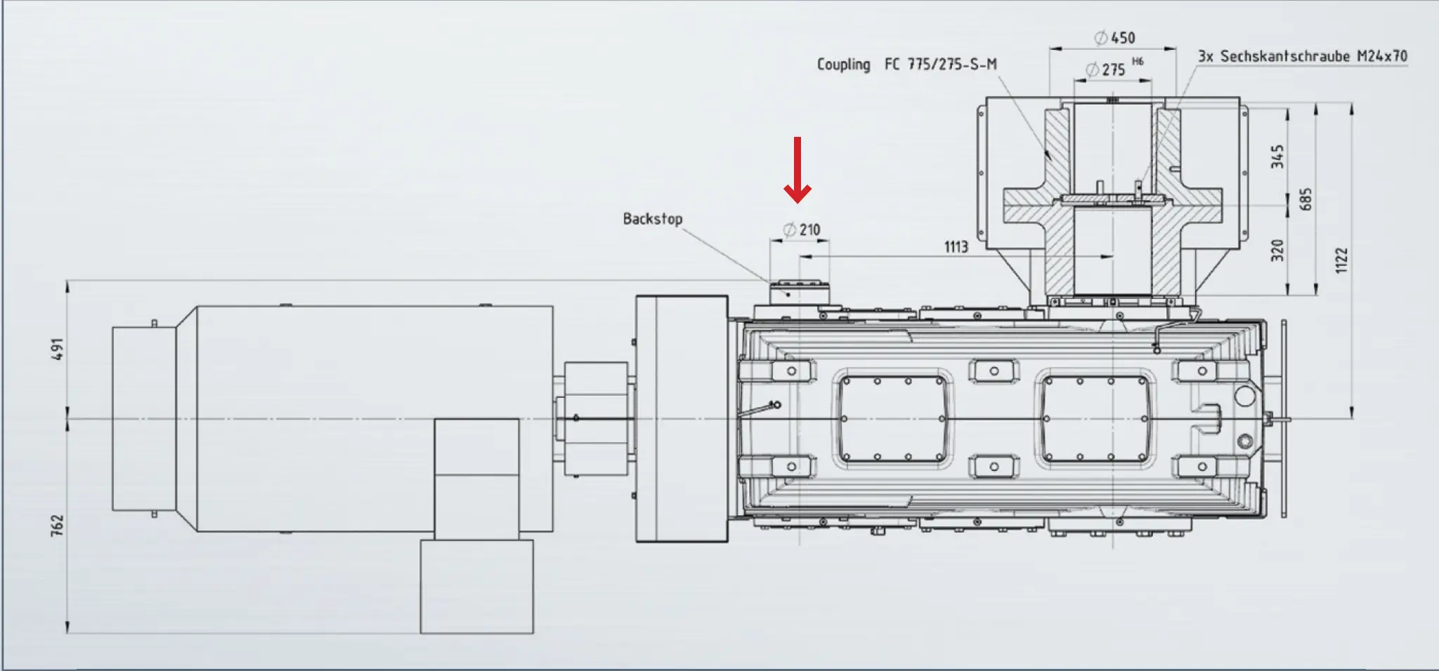
In this plan view of the drive, the rigid slow coupling can be seen embedded in the drive pulley shaft of the belt. In addition, on the same side of the reducer, the parking brake with which it is equipped can be seen.
First Backstop Failure
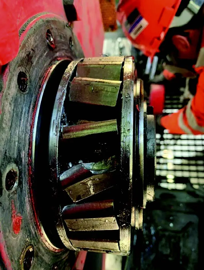
The stationary brake installed on the original drive is intended to prevent the sacrificial belt from going back one time that the motor has been un-energized. This stationary brake, chosen by the girdle manufacturer, is of the type known as the backstop. This brake, despite its good quality, failed catastrophically shortly after the start-up of the sacrificial belt, as seen in the attached image.
New Gearbox and New Brake
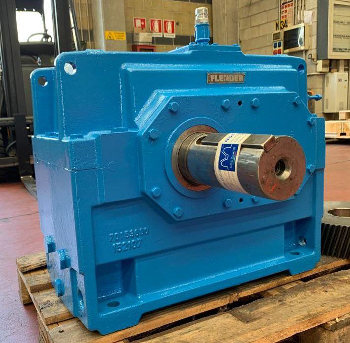
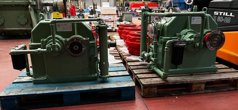
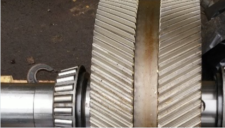
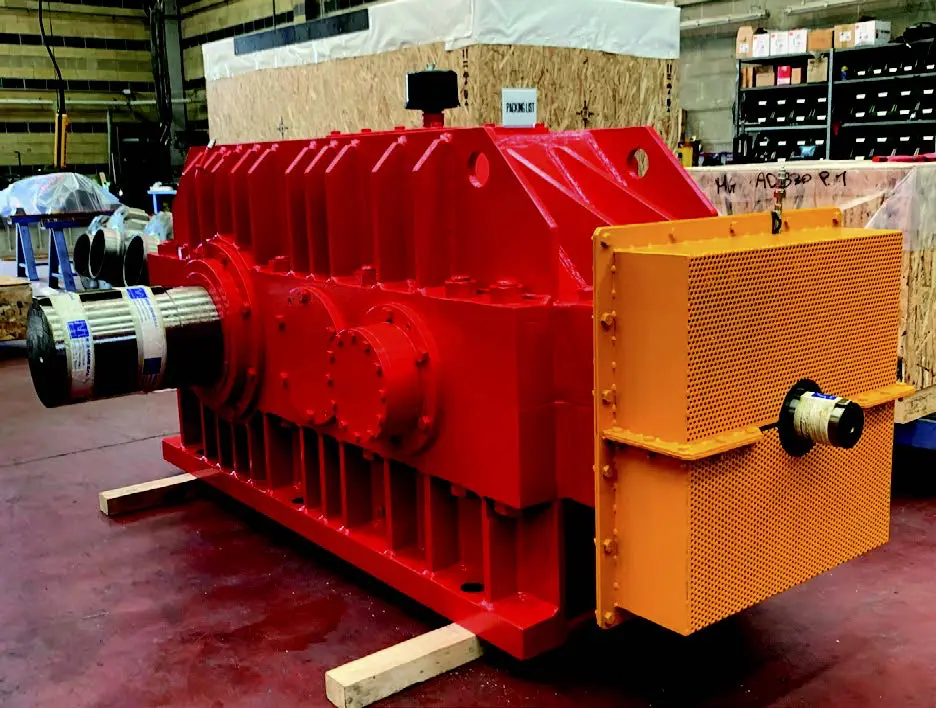
Failure of the backstop brake of the original drive damaged gearbox gears. SHP, therefore, decided to replace it with a new gearbox from MGS, supplied by Atlantic Bearing Services (ABS), equipped with a more robust backstop brake.
The second backstop installed on the new sacrificial belt drive gearbox failed severely in a relatively short period of time, so it was replaced by an even more robust one. This third backstop brake is still operating, but it has caused significant damage to some of the gears of the second gearbox.
ABS appointed a special technical commission to determine the origins of this problem and find practical solutions for it. The theoretical and practical aspects of this research are described in this project.
Theoretical-Practical Aspects Studied
- The belt conveyor.
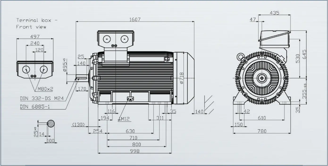
- The electric motor.
- The frequency converter.
- The gearbox.
- The backstop.
The Belt Conveyor

The Electric Motor
The Frequency Converter
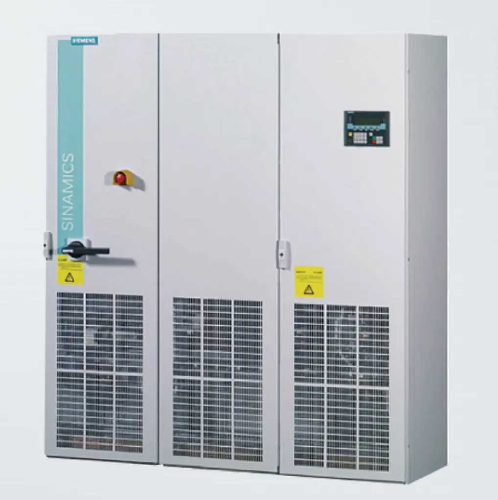
It is a four-quadrant frequency converter. This means that you can make the motor work both as a motor and as a brake in both forward and reverse direction. From a 50 to 60 Hz and 380 to 480 V line, it can generate 0 to 650 Hz and 0 to 480 V, with a current of up to 618 A, and a power of up to 332 kW. The high cost of this type of converter makes it find little in industrial drives, which they typically operate in one or two quadrants. This converter allows a great maneuvering capacity of the drive, as it does not require an operating brake. But in change, requires a special backstop.
The Gearbox
This is not a standard gearbox but a special gearbox designed for this application by ABS Atlantic Bearing Services and manufactured by MGS Gears, which has an AGMA service factor of 22 % higher than that of the original gearbox. This means that it has a fully satisfactory load capacity for the work normally to be performed on this drive.
The Backstop Brake
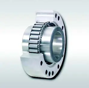
The backstop installed on the belt conveyor drive is intended to prevent the loaded belt from moving backwards once the motor has been un-energized. Many industrial belt conveyors have drives that work in one or two quadrants. In the first case, the drive can only drive the web forward. In the second case, the drive can additionally brake the strip dissipatively in its forward movement.
Conveyors with drives operating in one or two quadrants can use backstops as parking brakes. The drive cannot drive the belt backwards. Once the band stops in its movement and just begins to recoil, this brake blocks it in a turn of no more than 3°. If the backstop brake is placed on a high-speed shaft of the drive, the stop of the band is instantaneous.
In the Sacrificial Belt, the drive can slow down the forward movement of the belt in regenerative mode. When the belt stops, if this negative torque is maintained, the belt will try to go back, causing an impact on the backstop installed on a fast shaft of the reducer. Those impacts will quickly destroy the backstop brake in a drive that stops up to 50 times in 24 hours.
A more robust backstop will not appreciably extend its useful life and instead will subject the reducer gears to more severe punishment, causing them to deteriorate. Pictured is the result of the failure of the second backstop, a top-quality component carefully installed.
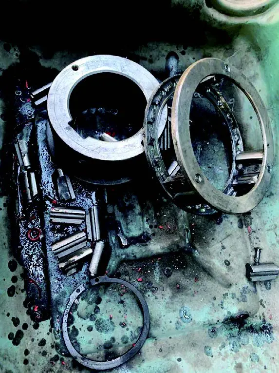
The roots of the problem posed by the failure of the backstops have become clear. The high maneuverability of the four-quadrant drive is not compatible with the use of backstops as stationary brakes. Backstops brakes are needed that do not block the reverse motion, but rather introduce enough torque to stop the belt from kicking back.
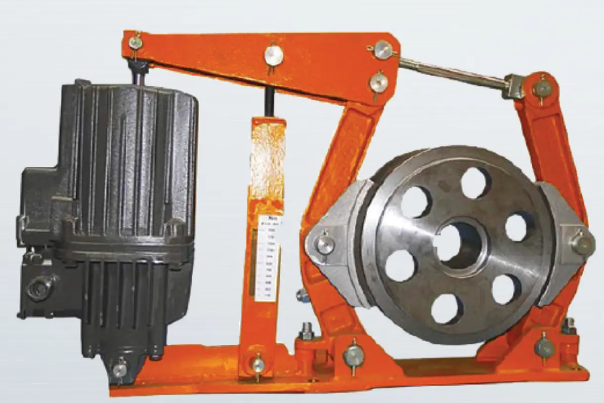
That requirement is fulfilled by the friction brakes, which allow a healthy slide, without predetermined limits, before stopping. An electro-hydraulically controlled friction pad brake suitable for this application is shown in the illustration.
This type of brake can be installed both on the motor shaft and on the drive pulley shaft. In this case, placement on the motor shaft places the brake right next to the motor, whose inertia is several times that of the rest of the conveyor and its load.
That way, most of the braking torque will be applied directly to the motor, and much less through the reducer to the conveyor and its load.
Conclusions
This Report has been a joint effort by various members of the ABS Technical Department, headed by Carlos Romay, with our ABS Representative in Peru, Nelson Del Portal, and with the enlightenment and decisive contribution of our scientific director, José Martínez Escanaverino. Likewise, the support of several professionals from Shougang Hierro Perú, including Vitto Guillén, has been precious.
